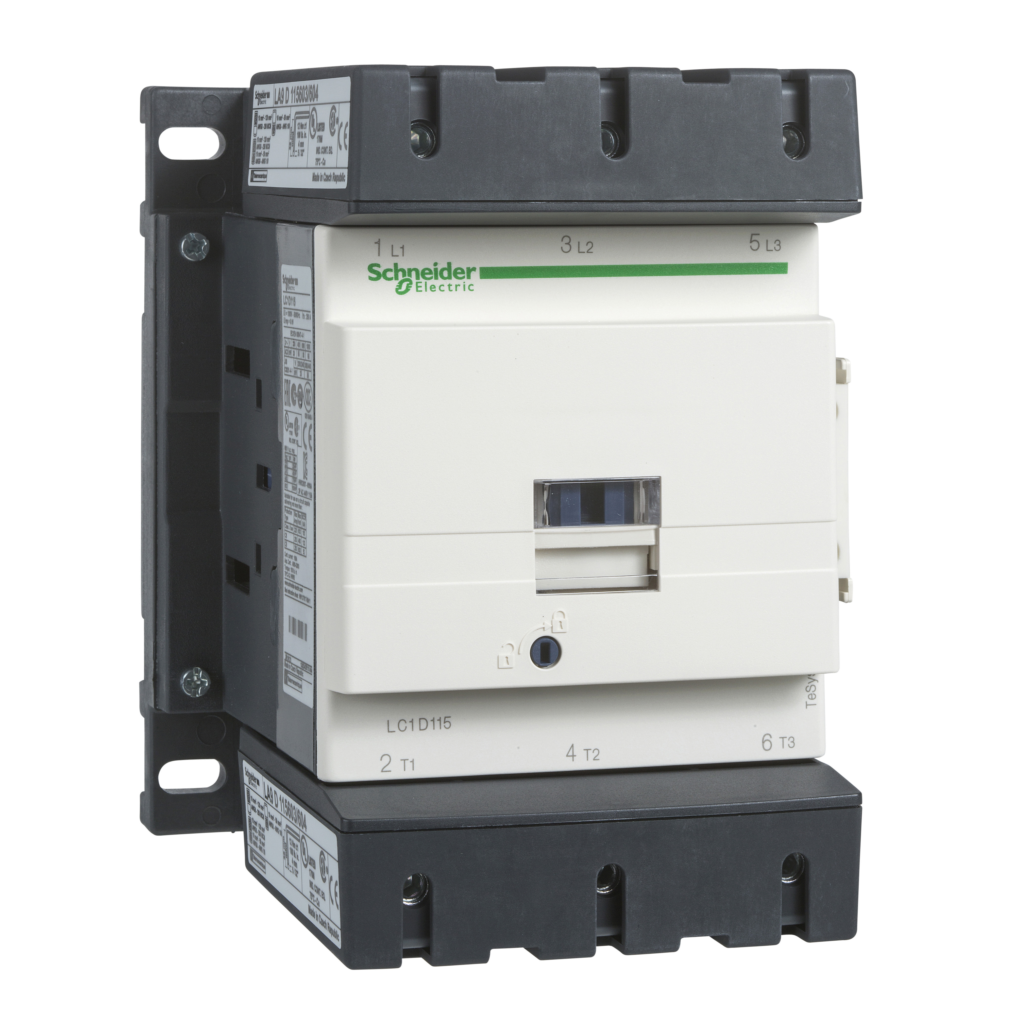
Schneider Electric TeSys™ D LC1D IEC Contactor With Protective Cover, 110 VAC Coil, 115 A Max Load, 3NO, 3 Poles
Contactors
61614
MFG #: LC1D115F7
Schneider Electric
569.46000
/ ea
- 360 Degree View URL - index.html?pid=11003&id=8087951360Den&ext=webp(360 Degree View URL)
- Brochure URL - 11003_9PT1LU7VOI5CXNW3.pdf(Brochure URL)
- Computer~Aided [CAD|BIM] Model URL - files?p_enDocType=CAD&p_File_Name=LC1D115F7_2D+Front+View.dwg(Computer~Aided [CAD|BIM] Model URL)
- Install Instructions 1 URL - files?p_File_Name=W915113010123-13.pdf(Install Instructions 1 URL)
- Seller Home Page URL - us(Seller Home Page URL)
- Service Manual URL - 11003_FDYOKJ53LVZH40R9.pdf(Service Manual URL)
- Spec Sheet 1 URL - Schneider_Electric_LC1D115F7_Datasheet.pdf(Spec Sheet 1 URL)
- Spec Sheet URL - 11003_NB70ZRSOLJY123X5.pdf(Spec Sheet URL)
- Tech Bulletin URL - 11003_8G547S3DJIOHPNLZ.pdf(Tech Bulletin URL)
- Tech Drawing URL - 11003_1IHVDJFTYLKOGP94.zip(Tech Drawing URL)
- Video - https://www.youtube.com/embed/e8UrRZljFg0(Video)
- Applications
- Features
| Resistive load;motor control |
| 30 HP 200/208 V AC 50/60 HZ 3 PHASE-40 HP 230/240 V AC 50/60 HZ 3 PHASE-75 HP 460/480 V AC 50/60 HZ 3 PHASE-100 HP 575/600 V AC 50/60 HZ 3 PHASE,BUILT-IN BIDIRECTIONAL PEAK LIMITING DIODE SUPPRESSOR |
| 200 A at 140 deg F power circuit conventional-free air thermal current |
| 1260 A at 440 V power circuit conforming to IEC 60947, 140 A AC signaling circuit conforming to IEC 60947-5-1, 250 A DC signaling circuit conforming to IEC 60947-5-1 IRMs rated making capacity |
| 1100 A at 440 V power circuit conforming to IEC 60947 rated breaking capacity |
| 200 A gG at 690 V coordination type 2-power circuit/250 A gG at 690 V coordination type 1 power circuit/10 A gG signaling circuit associated fuse rating |
| 0.6 mOhm at 50 Hz - Ith 200 A power circuit average impedance |
| Control circuit 10.62 in-lb (1.2 N-m) on screw clamp terminals with screwdriver flat 6 mm Dia tightening torque |
| 6 to 20 ms opening/20 to 50 ms closing operating time |
| 2400 cycles/hr at <=140 deg F (60 deg C) operating rate |
| Built-in bi-directional peak limiting diode suppressor coil technology |
| 280 to 350 VA at 68 deg F (20 deg C) 50/60 Hz inrush power |
| 2 to 18 VA at 68 deg F (20 deg C) 50/60 Hz hold-in power consumption |
| 3 to 8 W at 60 Hz heat dissipation |
| TH protective treatment |
| 3 pollution degree |
| -40 to 70 deg C permissible ambient air temperature around the device, -76 to 176 deg F storage temperature |
| 9842.52 ft without derating in temperature operating altitude |
| 1562 deg F (850 deg C) conforming to IEC 60695-2-1 fire resistance |
| V1 conforming to UL 94 flame retardance |
| Vibrations contactor open 2 gn, 5 to 300 Hz/vibrations contactor closed 4 gn, 5 to 300 Hz/shocks contactor closed 15 gn for 11 ms and shocks contactor open 6 gn for 11 ms mechanical robustness |
| 25 to 400 Hz signaling circuit frequency |

